
When it comes to expand its AWS network, some mistake can lead to security vulnerabilities or routing issues. You'll find below best practices and network architecture example.
This guide is aimed at platform engineers and cloud architects who are past the "one account, one VPC" phase and are dealing with the real complexity of multi-account, multi-region AWS environments. The most common mistakes at this stage are not conceptual — they are operational: CIDR ranges allocated ad-hoc that eventually overlap when you try to peer two VPCs, single-AZ deployments that look fine until there's an outage, and hub-and-spoke topologies stitched together with VPC peering that turn into an unmanageable mesh once you hit a dozen VPCs. Transit Gateway solves the mesh problem, but only if your route tables are designed from the start to enforce environment segregation. Getting these fundamentals right early is what separates a network that scales cleanly to 1,000 VPCs from one that requires painful re-IPing migrations later.
The golden rules
Rule #1: 1 VPC = 1 CIDR, maintain a list of them. It can be a basic excel file. The goal is to avoid IP range overlapping. This way you will be able to connect all your VPCs in the future without any routing conflict. That would lead in lost packets going in the wrong destination. You can pick up in the 3 private IP ranges:
- Classe A: 10.0.0.0/8 (10.0.0.0–10.255.255.255)
- Classe B: 172.16.0.0/12 (172.16.0.0–172.31.255.255)
- Class C: 192.168.0.0/16 (192.168.0.0–192.168.255.255)
CIDR planning for scale
If you are building toward tens or hundreds of VPCs, an ad-hoc spreadsheet will not survive contact with reality. You need a structured allocation strategy from day one.
A practical approach is to treat 10.0.0.0/8 as your supernet and divide it hierarchically by environment and region:
10.{env_octet}.{region_octet}.0/24

env_octet:
  0   → shared/management
  1   → production
  2   → staging
  3   → development
  4   → sandbox

region_octet (examples):
  1   → eu-west-1
  2   → eu-west-3
  3   → us-east-1
  4   → ap-southeast-1
With this scheme, a production VPC in eu-west-1 gets an address in 10.1.1.0/24, a staging VPC in us-east-1 gets 10.2.3.0/24, and so on. Each /24 gives you 256 addresses — enough for three layers of subnets across three AZs with room to spare, which is the right default for most application VPCs.
For enforcing and tracking allocations at scale, use AWS IPAM (IP Address Manager). IPAM integrates with AWS Organizations, so you can assign pools per OU and prevent any account from provisioning a VPC outside its allocated range. It also gives you a real-time view of utilization across all accounts — useful before you commit a new region or environment.
# Terraform example: IPAM pool for production eu-west-1
resource "aws_vpc_ipam_pool" "prod_euw1" {
  address_family = "ipv4"
  ipam_scope_id  = aws_vpc_ipam_scope.private.id
  locale         = "eu-west-1"
  description    = "Production pool — eu-west-1"
}

resource "aws_vpc_ipam_pool_cidr" "prod_euw1" {
  ipam_pool_id = aws_vpc_ipam_pool.prod_euw1.id
  cidr         = "10.1.1.0/20"  # room for 16 VPCs in this pool
}
The key constraint to remember: a /24 per VPC is the right default. It fits 3 AZs × 3 subnet tiers comfortably, avoids wasting address space, and keeps your supernet structured and predictable.
Rule #2: leverage availability zones (AZ), 2 for high availability or 3 for very high availability. For reminder, regions are split into multiple AZ. An AZ is composed by one or more datacenters. Each AZ has a different combination of utility providers: energy, water, internet… In case of outage of one provider, only one AZ would be affected. So, spreading your workload across multiple AZ will improve your tolerance and resilience to AZ failure.
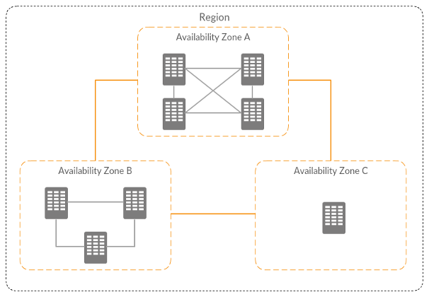
To go further in AZ failure management, when you create a new account, you can open a ticket to ask AWS to have the same AZ code/AZ id association. Example: eu-west-1a > euw1-az1. This way, if an AZ failed, it will be the same across all your accounts.
Rule #3: industrialization, leverage Infrastructure As Code (IaC) to avoid manual configuration mistakes and to ensure consistency. I recommend to script the deployments, but don't automate them because the network is a high risk component of your infrastructure.
Reference VPC architecture
This VPC is spreading across 3 AZ, and split into 3 layers:
- Public: for NAT gateways, load balancers, publicly exposed EC2 instances
- Private with internet access through NAT gateways: for EC2 instances
- Private without internet: for database, EFS, network resources…
Each layer serves a distinct purpose. The public tier handles inbound traffic from the internet — it is the only place where internet-facing load balancers and NAT gateways sit. The private-with-NAT tier hosts application workloads that need to reach the internet (to pull packages, call external APIs, or download updates) but must not be reachable from it. The private-isolated tier has no route to the internet at all — it is for databases, caches, and internal services where any outbound internet path is a security risk, not a feature.
It has an S3 gateway endpoint to avoid NAT gateway data processing cost if you have a lot of traffic between EC2 instances and S3 buckets.
VPC Flow Logs
Enable VPC Flow Logs on every VPC from day one. Send them to a centralized S3 bucket in your logging/audit account (not to individual account CloudWatch Logs groups, which fragments your visibility). A 90-day retention policy is a reasonable default — long enough to investigate incidents, short enough to control storage costs.
aws ec2 create-flow-logs \
  --resource-type VPC \
  --resource-ids vpc-0abc123def456 \
  --traffic-type ALL \
  --log-destination-type s3 \
  --log-destination arn:aws:s3:::your-central-flow-logs-bucket/vpc-logs/
Default security group
When a VPC is created, AWS provisions a default security group with rules that allow all inbound traffic from itself and all outbound traffic. Remove all rules from the default security group in every VPC and never assign it to any resource. Enforce this via the AWS Config managed rule restricted-default-security-group — it will flag any VPC where the default SG has rules, giving you continuous compliance monitoring across all accounts.
CIDRs example:
- VPC: 192.168.217.0/24
Public subnets:
- 192.168.217.0/28
- 192.168.217.16/28
- 192.168.217.32/28
Private subnets layer 1:
- 192.168.217.64/27
- 192.168.217.96/27
- 192.168.217.128/27
Private subnets layer 2:
- 192.168.217.160/27
- 192.168.217.192/27
- 192.168.217.224/27
Network evolution!
Your first project
1 project with multiple environment
There are 1 VPC per environment (ideally in different accounts to avoid the blast radius). They are isolated.
1 project with multiple environment + shared services
Each environment VPC is connected to a service VPC with a VPC peering.
Now let's scale!
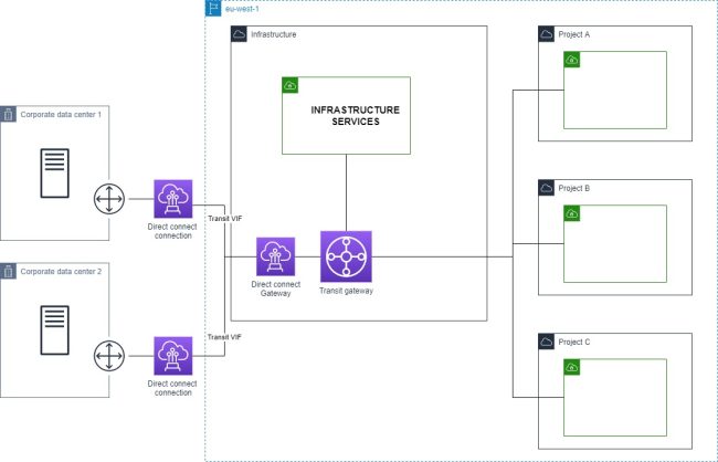
Multiple project + shared infrastructure service
The project VPC are connected to the infrastructure services VPC with a transit gateway.
The routing strategy of the transit gateway will depend of the traffic flows and your security requirements.
The star
Every VPC are isolated. They can access to the VPC service only, and the VPC service can access to all VPCs.
Here the related route tables associations and propagation:
- Purple arrow: propagation/route
- Green arrow: association
Environments segregation
Every VPCs from the same environment can communicate with each other.
Environment segregation + project shared services
You can have both transit gateway and VPC peering. You can also have only transit gateway if required by governance rules (example: traffic inspection, one centralized routing configuration…)
Transit Gateway route table design
The single most important TGW configuration decision is route table segregation. The default TGW configuration uses a single route table where every attachment propagates its routes and every attachment is associated — meaning every VPC can reach every other VPC. That is almost never what you want in a multi-environment setup.
The right approach is to create a separate route table per isolation domain:
- prod-rt: production VPCs associate here; propagates routes from production VPCs and shared services VPC only
- nonprod-rt: staging and development VPCs associate here; propagates routes from non-production VPCs and shared services VPC only
- shared-rt: the shared services VPC associates here; propagates routes from all VPCs so shared services can reach any environment
To actively prevent cross-environment routing, add blackhole routes. For example, in nonprod-rt, add a blackhole for your entire production CIDR block (10.1.0.0/16 in the scheme above). This means that even if a misconfiguration somehow adds a production route, the blackhole takes precedence and drops the traffic.
# Add a blackhole in nonprod route table to block prod traffic
aws ec2 create-transit-gateway-route \
  --transit-gateway-route-table-id tgw-rtb-nonprod \
  --destination-cidr-block 10.1.0.0/16 \
  --blackhole
For TGW peering across regions, use the same ASN on all Transit Gateways in your organization (e.g. 64512). This avoids ASN conflicts and simplifies BGP configuration when you also have on-premises connections.
Cost to plan for: each TGW attachment costs $0.05/hour (~$36/month) plus $0.02/GB of data processed through the TGW. In a large organization with many VPC attachments, TGW costs can become significant — factor this into your network design reviews.
Multiple project + shared infrastructure service + on-prem connection
VPN
Direct connect
Multiple direct connections
Multiple project + shared infrastructure service + on-prem connection + multiple regions
Regions are connected by transit gateway peering.
Network security controls
A common mistake is treating security groups and NACLs as interchangeable. They serve different purposes.
Security groups are stateful, operate at the instance/ENI level, and support allow rules only. They are your primary security control — design them to be as specific as possible (reference other security group IDs rather than CIDR ranges where possible).
NACLs are stateless, operate at the subnet level, and support both allow and deny rules. Because they are stateless, you must explicitly allow both inbound and outbound traffic including ephemeral ports (1024–65535). Use NACLs sparingly — their main practical use is as an emergency block at the subnet level when you need to drop traffic without modifying individual security groups.
AWS Network Firewall
For centralized egress inspection, deploy AWS Network Firewall in a dedicated inspection VPC. Traffic from spoke VPCs routes through the TGW to the inspection VPC, passes through the firewall, then exits via a NAT gateway to the internet. This pattern — sometimes called the centralized egress VPC — gives you one place to enforce and audit all outbound traffic rules across all environments.
Network Firewall supports stateful rules (Suricata-compatible rule strings) and stateless rules for high-throughput packet filtering, as well as managed threat intelligence rule groups maintained by AWS.
VPC Endpoints
Prefer VPC Endpoints over NAT Gateway for AWS service traffic:
- Gateway endpoints (S3, DynamoDB): free, no per-hour or per-GB charge. Add these to every VPC that touches S3 or DynamoDB.
- Interface endpoints (all other AWS services): $0.01/hour per AZ plus $0.01/GB. Evaluate based on your data transfer volume — for high-volume services like SQS, ECR, or Secrets Manager, the endpoint cost is typically lower than the equivalent NAT Gateway data processing charge.
In a multi-account setup, deploy interface endpoints centrally in the shared services VPC and share them with spoke VPCs via Route 53 Private Hosted Zones and TGW routing. This avoids duplicating endpoint costs across every account.
Monitoring your network
As your network grows, manual review of route tables and security group rules does not scale. You need tooling.
VPC Flow Logs + Athena: Flow Logs stored in S3 can be queried with Athena directly. Create a partition-projected Athena table over your flow logs bucket to query traffic patterns, top talkers, and rejected connections without loading data into a separate system.
-- Top rejected connections by source IP in the last 7 days
SELECT srcaddr, dstaddr, dstport, protocol, COUNT(*) as count
FROM vpc_flow_logs
WHERE action = 'REJECT'
  AND year = '2026' AND month = '04'
GROUP BY srcaddr, dstaddr, dstport, protocol
ORDER BY count DESC
LIMIT 50;
Reachability Analyzer: when a connectivity issue is reported, Reachability Analyzer traces the path between a source and destination through your network components (security groups, NACLs, route tables, TGW route tables) and tells you exactly where the packet is dropped and why. Far faster than manually auditing each component in sequence.
Network Access Analyzer: use this for compliance and audit workflows. Define network access scopes (e.g. "no internet-reachable paths should exist to any RDS instance") and run periodic analyses to detect violations before they become incidents.
Topology visualization: when your network grows to tens of VPCs, manually tracing TGW attachments, peering connections, and route table associations across accounts becomes error-prone. VizCon auto-generates your full network topology diagram on demand — showing all VPCs, TGW attachments, peering connections, and security group rules in a single view. This makes it practical to verify that your TGW route table isolation is actually working as intended: you can see at a glance whether any unexpected cross-environment path exists, without hunting through dozens of route tables manually.
Conclusion
From these architecture example, you could implement features like centralized VPC endpoints, traffic inspection, centralized internet access…
Some says network is hard. But it's all logic and predefined rules. Following the golden rules, and with the right tools like VizCon, it will be easy peasy.